YFYBW
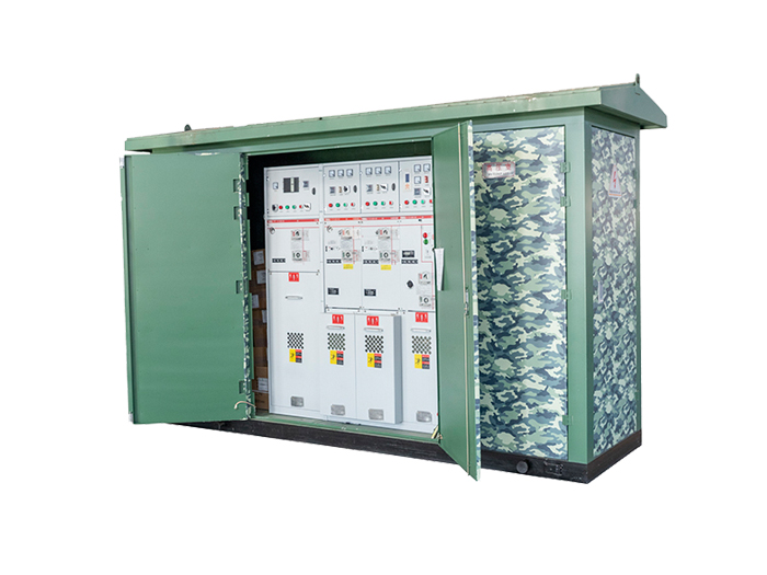
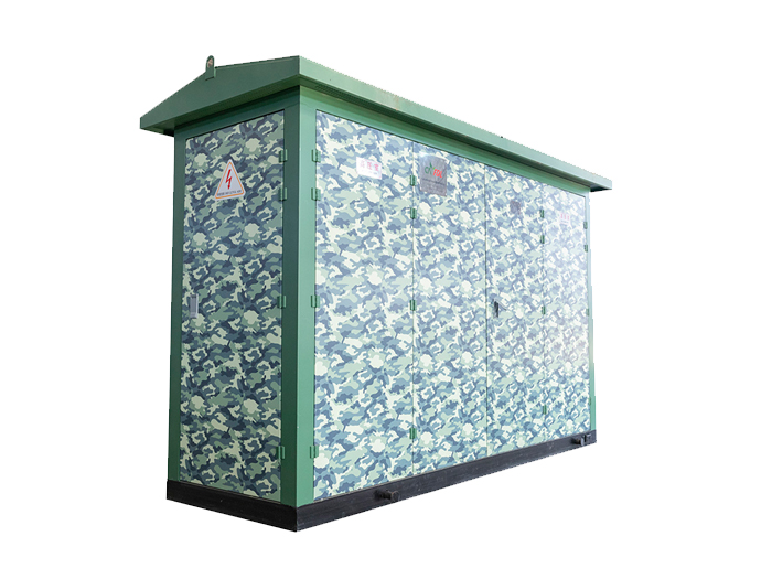
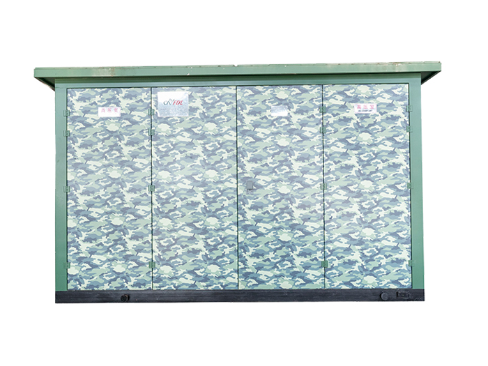
The YFYBW 35 kV Eco-Friendly Combined Substation is an integrated assembly that incorporates medium-voltage switchgear, transformer, and low-voltage distribution equipment into a single unit. Serving as a power distribution solution for urban buildings, residential communities, small-to-medium industrial plants, and mining/oilfield facilities, it features high integration degree, compact structure with minimized footprint, enhanced reliability, reduced on-site installation workload, shortened commissioning cycles, and relocatable design. Through customized exterior styling and color schemes to harmonize with surrounding environments, it additionally provides aesthetic integration with urban landscapes. This product represents a modern replacement for conventional civil-engineered substations in both urban and rural areas, and serves as an advanced integrated solution for urban grid development and renovation projects.


Specification Parameter
| Item | Unit | High voltage electrical equipment | Transformer | Low voltage electrical equipment | |
| Rated voltage | kV | 7.2,12 | 6/0.4、 10/0.4 | 0.4 | |
| Rated capacity | kvA | type:200-1250 | |||
| type:50-400 | |||||
| Rated current | A | 200-630 | 100-3000 | ||
| Rated breaking current | A | Load switch400-630A | 15-63 | ||
| kA | Combined electrical equipment is dependent on fuse | ||||
| Rated short time withstand current | kA (xs) | 20x(2) | 200-400kvA | 15X1 | |
| (12.5x4) | 400kvA | 30X1 | |||
| Brought forward | ||||
| Item | Unit | High voltage electrical equipment | Transformer | Low voltage electrical equipment |
| Rated peak withstand current | kA | 31.5, 50 | 200-400kvA | 30 |
| 400kvA | 63 | |||
| Rated closing current | kA | 31.5, 50 | ||
| Line frequency withstand voltage | kV | Phase to earth and phase similar32, 40 | Oilimmersion:35/5min | <300V±2kV |
| Isolated fracture34,48 | Dry type:28/5min | 300,600V±2.5kV | ||
| Thunder stroke impact | kV | Phase to earth and phase similar60:75 | 75 | |
| lsolated fracture75, 85 | 75 | |||
| Noise level | dB | Oilimmersion:<55 | ||
| Dry type:<65 | ||||
| Protection grade | IP23D | |||
| Outline dimension | Choose different outline dimension according to the capacity and mode of selected transformer. | |||
Product Advantage
1. Substation Configuration The substation comprises HV switchgear room, LV switchgear room, relay protection room, and transformer room. HV/LV switchgear rooms and relay protection room enclosures may be fabricated from:Aluminum alloy panels (surface-treated with anodization for enhanced corrosion resistance and structural strength), Steel plates (all structural steel components treated with phosphating), or Composite panels (offering vibrant aesthetics with thermal insulation and flame-retardant properties). Transformer room features an elevated safety mesh enclosure (non-enclosed structure) to ensure: (i) Optimal transformer ventilation and heat dissipation, (ii) Personnel and equipment safety compliance.

2. HV Switchgear Room
Accommodates JYN1-35, KYN10-35 switchgear units, or 35 kV load-break switches.
35 kV line configurations (incoming/outgoing) support user-selectable overhead lines or cable terminations.
3. LV Switchgear Room
a. For 10 kV LV-side applications (Note: Typically denotes medium-voltage distribution; "LV-side" likely refers to secondary distribution voltage level):
Installable equipment: XGN2-10, KZN1-12, KYN1-12 switchgear; HXGN11-10F, HXGN26-10(F) ring-main units (RMUs).
b. For 0.4 kV LV-side applications:
Space-optimized design (typically without dedicated LV switchgear cabinets) houses:Low-voltage power circuit breakers: DW15T, ME, M, F series air-break frame-type circuit breakers.
Molded-case circuit breakers (MCCBs): DZ20, CM, H, S series.
4. Relay Protection Room
Houses AC/DC power panels, signaling panels, protection relays, SCADA interface panels (RTU), carrier communication units, or fiber-optic terminal equipment.
Protection System Options (per user requirement):Conventional electromagnetic relay protection or substation microprocessor-based integrated automation system.
Outline And Mounting Dimensions