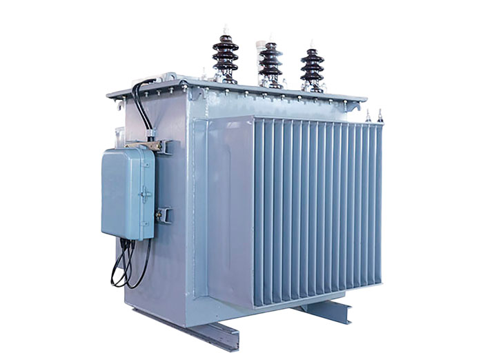
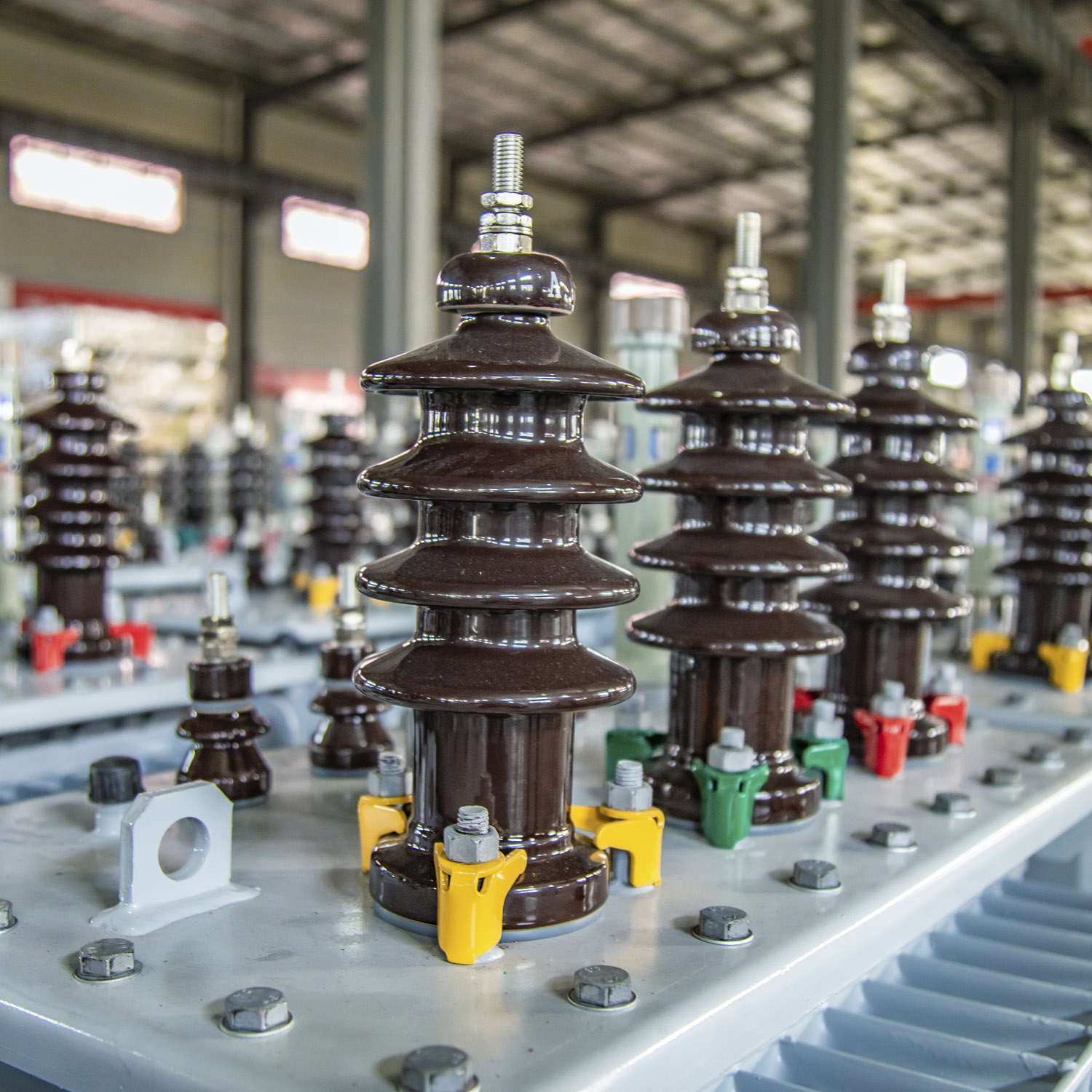
S11 Series 10KV Distribution Transformer
Essential for high-voltage power systems, these transformers use oil-cooled iron cores and windings to ensure efficient insulation, heat dissipation, and durability. Ideal for substations and industries, they provide overload capacity and extended service life with routine maintenance.


Specification Parameter
30kVA-2500kVA Three-phase duplex winding non-excited tap-changing distribution transformer
| Rated capacity (kVA) | Voltage Combin and Tap range | Vector group Symbol | Loss(kW) | No-load current(%) | Impedance voltage | Weight (T) | Boundary dimension(mm) LxWxH | Gauge vertical/ horizontal(mm) | ||||||
| HV(kV) | HV Tap Range | LV (kV) | No-load | Load | Body | Oil | Total | Omniseal | Un-omniseal | |||||
| 30 | 6 6.3 10 10.5 11 | ±5 ±2×2.5 | 0.4 | Dynll Yznll Yyn0 | 0.10 | 0.63/0.60 | 2.3 | 40 | 0.22 | 0.10 | 039 | 1050×570×1100 | 1105×570×1185 | 350/400 |
| 50 | 0.13 | 0.91/0.87 | 2.0 | 0.28 | 0.12 | 0.53 | 1080×600×1150 | 1080×600×1120 | 350/400 | |||||
| 63 | 0.15 | 1.09/1.04 | 1.9 | 035 | 012 | 0.59 | 1100×635×1150 | 1100×635×1300 | 350/400 | |||||
| 80 | 0.18 | 131/1.25 | 1.9 | 0.41 | 0.14 | 0.67 | 1150×675×1095 | 1150×675×1245 | 400/400 | |||||
| 100 | 0.20 | 1.58/1.50 | 1.8 | 047 | 015 | 0.75 | 170×710×1220 | 1170×715×1370 | 450/400 | |||||
| 125 | 0.24 | 1.89/1.80 | 1.7 | 0.53 | 0.16 | 0.83 | 1230×740×1270 | 1230×740×1420 | 550/550 | |||||
| 160 | 0.28 | 2.31/2.20 | 1.6 | 062 | 0.18 | 0.96 | 980×650×1230 | 1320×800×1410 | 550/550 | |||||
| 200 | 0.34 | 2.73/2.60 | 1.5 | 0.69 | 0.20 | 1.09 | 1000×730×1280 | 1330×770×1510 | 550/550 | |||||
| 250 | 0.40 | 3.20/3.05 | 1.4 | 0.84 | 0.23 | 1.28 | 1180×740×1230 | 1380×770×1530 | 550/550 | |||||
| 315 | 0.48 | 3.83/3.65 | 1.4 | 0.98 | 0.24 | 1.47 | 1240×800×1330 | 1500×870×1610 | 550/550 | |||||
| 400 | 0.57 | 4.52/4.30 | 1.3 | 1.03 | 0.30 | 1.62 | 1340×880×1260 | 1550×900×1650 | 550/550 | |||||
| 500 | 0.68 | 5.41/5.15 | 1.2 | 1.37 | 0.31 | 2.04 | 1430×960×1310 | 1680×970×1730 | 660/660 | |||||
| 630 | Dynll Yyn0 | 0.81 | 6.20 | 1.1 | 4.5 | 1.53 | 0.45 | 2.33 | 1510×950×1420 | 1700×970×1850 | 660/660 | |||
| 800 | 0.98 | 7.50 | 1.0 | 1.710 | 0.49 | 2.67 | 1750×985×1650 | 1750×985×1980 | 820/820 | |||||
| 1000 | 1.15 | 10.30 | 1.0 | 2.20 | 0.57 | 3.10 | 1840×1140×1770 | 1840×1040×1970 | 820/820 | |||||
| 1250 | 1.36 | 12.00 | 0.9 | 2.47 | 0.67 | 3.70 | 1930×1200×1810 | 1930×1200×2020 | 820/820 | |||||
| 1600 | 1.64 | 14.50 | 0.8 | 2.85 | 0.79 | 4.20 | 2100×1300×1930 | 2100×1300×2150 | 820/820 | |||||
| 2000 | 1.96 | 17.80 | 0.5 | 3.75 | 0.98 | 4.84 | 2150×1640×1950 | 2150×1640×2170 | 1070/1070 | |||||
| 2500 | 2.31 | 20.70 | 0.4 | 3.72 | 1.18 | 5.76 | 2160×1750×1970 | 2160×1750×2190 | 1070/1070 | |||||
| 630KVA~6300KVA 3-phase duplex winding non-excited tap-changing power transformer | ||||||||||||
| Rated capacity (kVA) | Voltage Combination and Tap range | Vector group Symbol | Loss(kW) | No-load current(% | oltage | Weight(T) | Gauge vertical/ horizontal(mm) | |||||
| HV(kV) | HVTap Range(%) | LV(kV) | No-load | Load | Body | Oil | Total | |||||
| 630 | 6 6.3 10 10.5 11 | ±5 ±2×2.5 | 3 3.15 6.3 | Yd11 | 0.84 | 6.93 | 1.1 | 5.5 | 1.78 | 0.45 | 2.71 | 750/660 |
| 800 | 1.02 | 8.46 | 1.0 | 2.10 | 0.52 | 3.31 | 850/660 | |||||
| 1000 | 1.20 | 9.92 | 1.0 | 2.58 | 0.60 | 3.86 | 850/820 | |||||
| 1250 | 1.42 | 11.80 | 0.9 | 2.88 | 0.70 | 4.37 | 850/820 | |||||
| 1600 | 1.71 | 14.11 | 0.8 | 3.40 | 0.78 | 4.76 | 900/820 | |||||
| 2000 | 2.04 | 16.93 | 0.8 | 3.80 | 0.89 | 5.57 | 900/820 | |||||
| 2500 | 2.40 | 19.67 | 0.8 | 4.35 | 0.96 | 6.67 | 1070/1070 | |||||
| 3150 | 2.84 | 23.09 | 0.7 | 4.94 | 1.18 | 8.50 | 1070/1070 | |||||
| 4000 | 10 10.5 11 | 3.1563 | 3.48 | 27.36 | 07 | 5.90 | 1.58 | 9.85 | 1070/1070 | |||
| 5000 | 4.16 | 31.38 | 0.7 | 6.85 | 1.76 | 11.58 | 1070/1070 | |||||
| 6300 | 4.96 | 35.06 | 0.6 | 7.92 | 1.91 | 13.65 | 1070/1070 | |||||
| Note 1:According to requirements,the transformer can supply HVtap change±2×2.5%. | ||||||||||||
| 200KVA~2500KVA3-phase duplex winding on-load tap-changing distribution transformer | ||||||||||||
Rated capacity (kVA) | Voltage Combination and Tap range | Vector group Symbol | Loss(kW) | No-load) current(% | Impedance voltage | Weight(T) | Gauge vertical/ horizontal(mm) | |||||
| HV(kV) | HV Tap Range (% | LV(kV) | No-load | Load | Body | Oil | Total | |||||
| 200 | 6 6.3 10 | ±4×2.5 | 0.4 | Dnyll Yyn0 | 0.39 | 2.91 | 1.5 | 4.0 | 0.98 | 0.26 | 1.53 | 550/550 |
| 250 | 0.45 | 3.42 | 1.4 | 1.07 | 0.31 | 1.74 | 650/550 | |||||
| 315 | 0.54 | 4.10 | 1.4 | 1.32 | 0.35 | 1.98 | 650/550 | |||||
| 400 | 0.65 | 4.96 | 1.3 | 1.58 | 0.43 | 2.27 | 750/550 | |||||
| 500 | 0.77 | 5.90 | 1.2 | 1.75 | 0.45 | 2.50 | 750/660 | |||||
| 630 | 0.97 | 7.27 | 1.1 | 4.5 | 1.90 | 0.53 | 2.92 | 750/660 | ||||
| 800 | 1.13 | 8.89 | 1.0 | 2.15 | 0.60 | 3.32 | 850/660 | |||||
| 1000 | 1.38 | 10.43 | 1.0 | 2.48 | 0.68 | 3.71 | 850/820 | |||||
| 1250 | 1.58 | 12.40 | 0.9 | 2.62 | 0.77 | 4.20 | 850/820 | |||||
| 1600 | 1.94 | 14.79 | 0.8 | 3.10 | 0.88 | 4.85 | 900/820 | |||||
| 2000 | 2.27 | 18.69 | 0.6 | 3.98 | 1.08 | 5.88 | 900/820 | |||||
| 2500 | 252 | 21.74 | 0.6 | 3.95 | 1.30 | 6.37 | 1070/1070 | |||||
| Note1:According to requirements,the transformer can supply HV winding voltage 10.5KVand 11KV. Note2:According to requirements,the transformer can supply LV0.69KV. | ||||||||||||
Product Advantage
1. Voltage conversion and energy transfer :
The core function of a distribution transformer is to change voltage. It can reduce high voltage to a voltage suitable for the
distribution network, and at the same time adjust the current to an appropriate level, thereby achieving effective transmission of electrical energy.
2.Improving power transmission efficiency and safety:
By reducing voltage, distribution transformers can reduce energy losses during power transmission, thereby improving
the efficiency of the entire power system.
Outline And Mounting Dimensions