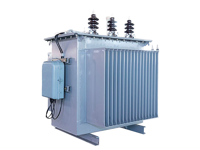
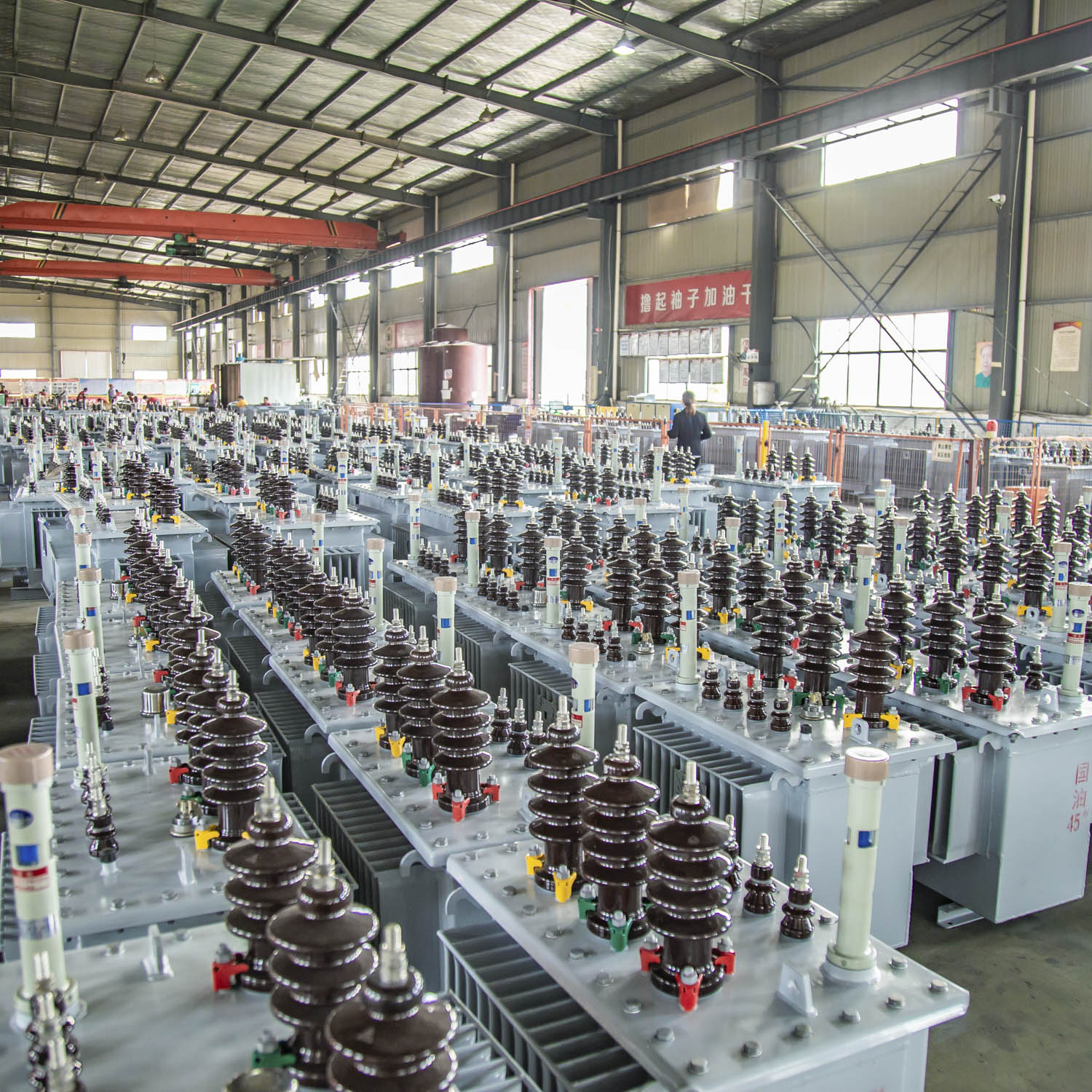
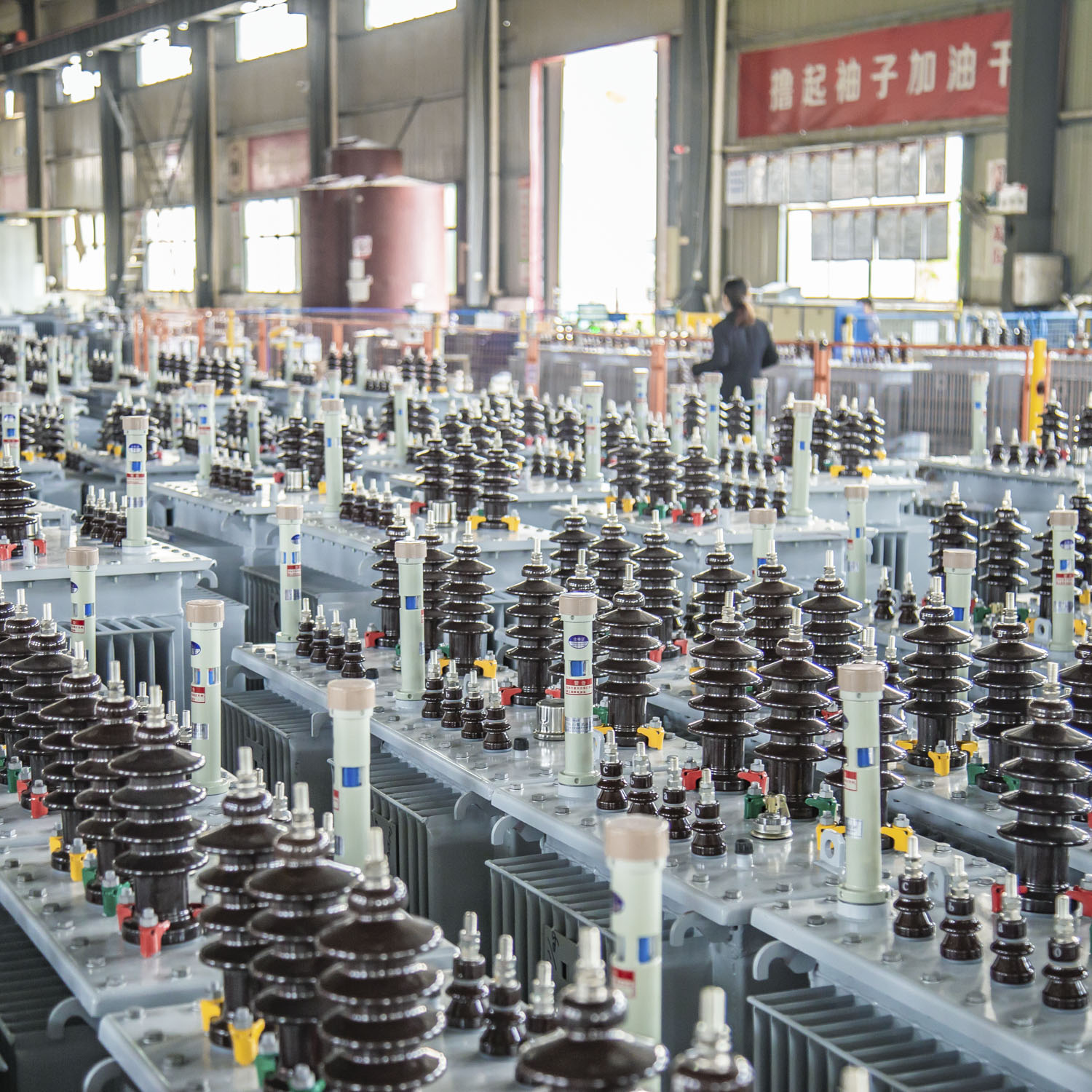
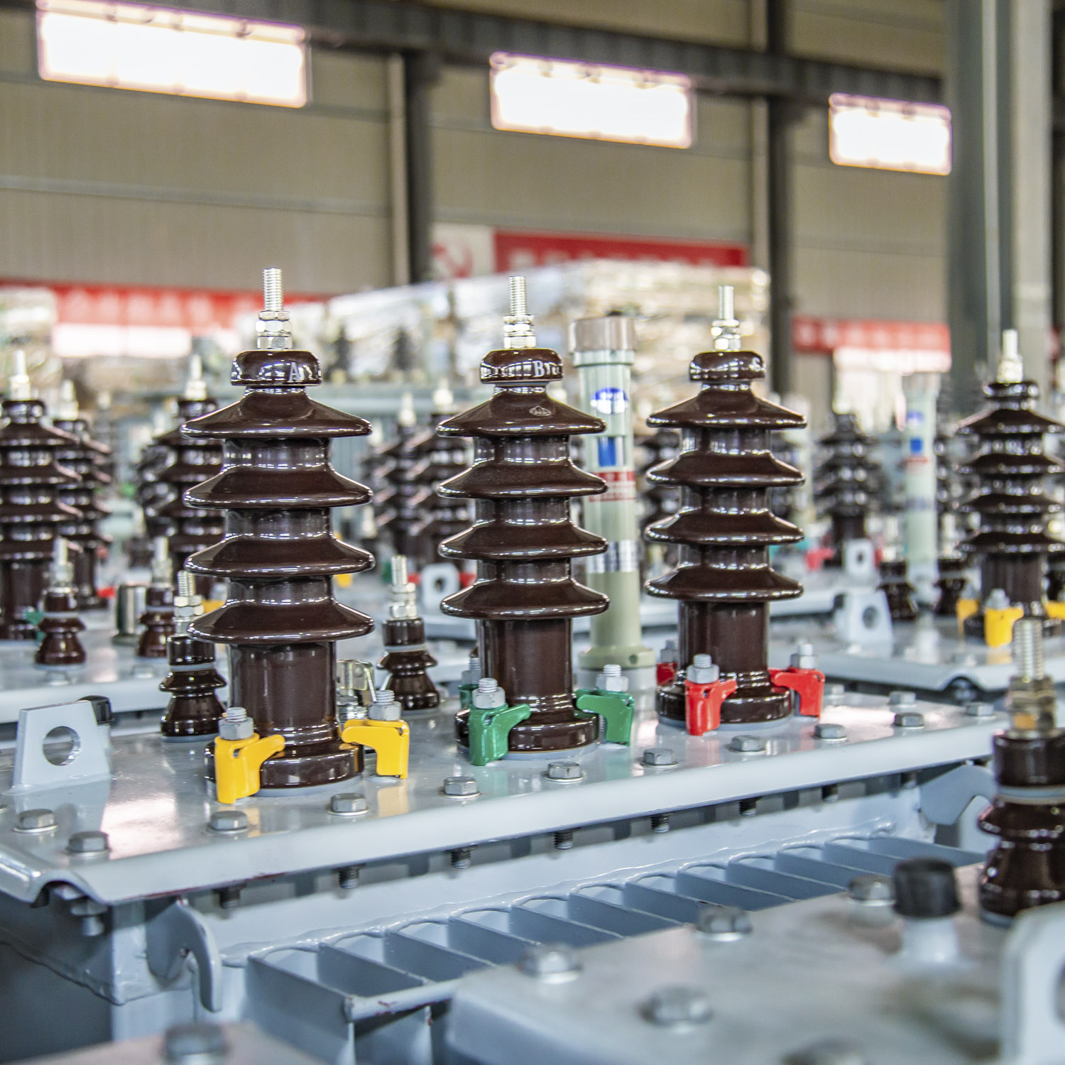
S10 Series 10KV Distribution Transformer
Essential for high-voltage power systems, these transformers use oil-cooled iron cores and windings to ensure efficient insulation, heat dissipation, and durability. Ideal for substations and industries, they provide overload capacity and extended service life with routine maintenance.

Specification Parameter
| 30KVA~2500KVA Three-phase duplex winding non-excited tap-changing distribution transformer | ||||||||||||||
| Rated capacity (kVA) | Voltage Combination and Tap range | Vector group symbol | Loss(kW) | No-load current(%) | Impedance voltage | Weight (T) | boundarydimension(nm) LxWxH | Gauge vertical horizontal (mm) | ||||||
| HV (kV) | HV Tap Range | LV(kV) | No-load | Load | Omniseal | Un-omniseal | ||||||||
| Body | Oil | Total | ||||||||||||
| 30 | 6 6.3 10 10.5 11 | ±5 ±2×2.5 | 0.4 | Dn11 Yzn1 Yyn0 | 0.11 | 0.63/0.60 | 2.0 | 0.21 | 0.08 | 0.32 | 1000x550x1050 | 1065x550x1135 | 400/400 | |
| 50 | 0.15 | 0.91/0.87 | 1.9 | 0.275 | 0.09 | 0.43 | 1050x580x1100 | 1105x670x1185 | 450/400 | |||||
| 63 | 0.18 | 1.09/1.04 | 1.8 | 0.316 | 0.10 | 0.50 | 1080x600x1150 | 1135x685x1120 | 450/400 | |||||
| 80 | 0.20 | 1.31/1.25 | 1.7 | 0.37 | 0.12 | 0.52 | 1100x635x1150 | 1100x630x1300 | 450/400 | |||||
| 100 | 0.23 | 1.58/1.50 | 1.55 | 0.40 | 0.12 | 0.58 | 1150x675x1095 | 1150x670x1245 | 450/400 | |||||
| 125 | 0.27 | 1.89/1.80 | 1.45 | 4.0 | 0.48 | 0.15 | 0.70 | 1170×710×1220 | 1170×710×1370 | 550/400 | ||||
| 160 | 0.31 | 2.31/2.20 | 1.3 | 0.56 | 0.17 | 0.83 | 1230x740x1270 | 1230x740x1410 | 550/550 | |||||
| 200 | 0.38 | 2.73/2.60 | 1.2 | 0.65 | 0.17 | 1.05 | 1320x760x1290 | 1320x760x1420 | 550/550 | |||||
| 250 | 0.46 | 3.20/3.05 | 1.1 | 0.75 | 0.22 | 1.12 | 1330x760x1360 | 1330x760x1510 | 650/550 | |||||
| 315 | 0.54 | 3.83/3.65 | 1.0 | 0.85 | 0.23 | 1.30 | 1380×780×1380 | 1380×760×1530 | 650/550 | |||||
| 400 | 0.65 | 4.52/4.30 | 1.0 | 1.03 | 0.30 | 1.62 | 1500x860x1460 | 1500x830x1610 | 750/550 | |||||
| 500 | 0.78 | 5.41/5.15 | 1.0 | 1.20 | 0.32 | 1.85 | 1550x890x1500 | 1550x890x1650 | 750/660 | |||||
| 630 | Dyn11Yyn0 | 0.92 | 6.20 | 0.8 | 4.5 | 1.53 | 0.44 | 2.31 | 1680x960x1580 | 1680x960x1730 | 750/660 | |||
| 800 | 1.12 | 7.50 | 0.7 | 1.71 | 0.49 | 2.67 | 1700x960x1580 | 1700x960x1850 | 850/660 | |||||
| 1000 | 1.32 | 10.30 | 0.6 | 2.01 | 0.56 | 3.05 | 1750x1080x1650 | 1750x1080x1950 | 850/820 | |||||
| 1250 | 1.56 | 12.00 | 0.6 | 2.37 | 0.66 | 3.57 | 1840x1140x1770 | 1840x1140x1970 | 850/820 | |||||
| 1600 | 1.88 | 14.50 | 0.6 | 2.70 | 0.79 | 3.95 | 1930x1300x1810 | 1930x1300x2020 | 900/820 | |||||
| 2000 | 2.27 | 17.80 | 0.5 | 3.65 | 0.90 | 4.65 | 2100x1640x1930 | 2100x1640x2170 | 900/820 | |||||
| 2500 | 2.67 | 2070 | 0.4 | 3.72 | 0.98 | 5.76 | 2120x1750x1970 | 2120x1750x2190 | 1070/1070 | |||||
| Note 1:The load loss above the oblique line in the table applies to Dyn11 or Yzn11;the load loss below the obligue lineapplies to Yyn0. | ||||||||||||||
| 630KVA-6300KVA3-phaseduplex winding non-excited tap-changing power transformer | ||||||||||||
| Rated capacity (KVA) | Voltage Combination and Tap range | Vector group Symbol | LosskW | No-load current (%) | Impedance voltage | Weight(T) | Gauge verticalí horizontal(mm) | |||||
| HVIkV) | HVTap Rangel%) | LVIKV) | No-oad | Load | Body | Oil | Total | |||||
| 630 | 6 6.3 10 10.5 11 | ±5 ±2×2.5 | 3 3.15 6.3 | Yd11 | 0.82 | 6.95 | 1.1 | 5.5 | 1.65 | 0.45 | 2.61 | 750/660 |
| 800 | 1.01 | 8.46 | 1.0 | 1.90 | 0.52 | 3.11 | 850/660 | |||||
| 1000 | 1.18 | 9.92 | 1.0 | 2.18 | 0.60 | 3.66 | 850/820 | |||||
| 1290 | 1.40 | 11.80 | 0.9 | 2.48 | 0.70 | 4.07 | 850/820 | |||||
| 1600 | 1.69 | 14.11 | 0.8 | 2.68 | 0.78 | 4.46 | 900/820 | |||||
| 2000 | 2.02 | 16.93 | 0.8 | 3.10 | 0.89 | 5.27 | 900/820 | |||||
| 2500 | 2.38 | 19.67 | 0.8 | 3.82 | 0.96 | 6.37 | 1070/1070 | |||||
| 3150 | 2.81 | 23.09 | 0.7 | 4.44 | 1.18 | 7.80 | 1070/1070 | |||||
| 4000 | 10 10.5 11 | 3.15 6.3 | 3.46 | 27.36 | 0.7 | 5.30 | 1.55 | 9.35 | 1070/1070 | |||
| 5000 | 4.10 | 31.38 | 0.7 | 6.25 | 1.76 | 11.08 | 1070/1070 | |||||
| 6300 | 4.90 | 35.06 | 0.6 | 7.32 | 1.95 | 13.15 | 1070/1070 | |||||
| Note 1:According to requirements,the transformercan supply HVtap change±2×2.5% | ||||||||||||
| 200KVA~2500KVA3-phase duplex winding on-load tap-changing distribution transformer | ||||||||||||
| Rated capacity (kVA) | Valtage Combination and Tap range | Vector group Symbol | LosskW) | No-load current (%) | Impedance voltage | Weight (T) | Gauge vertical/horizontal | |||||
| HV(KV) | HV Tap Rangel1%) | LVIKV) | No-load | Load | Body | Oil | Total | |||||
| 200 | 6 6.3 10 | ±4×2.5 | 0.4 | Dny11 Yyn0 | 0.38 | 2.91 | 1.5 | 4.0 | 0.88 | 0.26 | 1.43 | 550/550 |
| 250 | 0.45 | 3.42 | 1.4 | 0.97 | 0.31 | 1.64 | 650/550 | |||||
| 315 | 0.54 | 4.10 | 1.4 | 1.12 | 0.35 | 1.78 | 650/550 | |||||
| 400 | 0.64 | 4.96 | 1.3 | 1.28 | 0.43 | 2.07 | 750/550 | |||||
| 500 | 0.77 | 5.90 | 1.2 | 1.45 | 0.45 | 2.30 | 750/660 | |||||
| 630 | 0.96 | 7.27 | 1.1 | 4.5 | 1.70 | 0.53 | 2.72 | 750/660 | ||||
| 800 | 1.12 | 8.89 | 1.0 | 1.95 | 0.60 | 3.12 | 850/660 | |||||
| 1000 | 1.36 | 10.43 | 1.0 | 2.218 | 0.68 | 3.51 | 850/820 | |||||
| 1250 | 1.56 | 12.40 | 0.9 | 2.42 | 0.77 | 4.00 | 850/820 | |||||
| 1600 | 1.92 | 14.19 | 0.8 | 2.87 | 0.88 | 4.650 | 900/820 | |||||
| 2000 | 2.268 | 18.69 | 0.6 | 3.87 | 0.99 | 5.51 | 900/820 | |||||
| 2500 | 2.52 | 21.74 | 0.6 | 3.94 | 1.08 | 6.75 | 1070/1070 | |||||
| Note1:According to requirements,the transformer can supply HV winding voltage 10.5KV and 11KV. Note2:According to requiremens,the transformer can supply LV 0.69KV. | ||||||||||||
Product Advantage
1. Superior cooling efficiency
Insulating oil provides excellent heat dissipation, allowing higher overload capacity and sustained performance in high-load scenarios (e.g., 1.3× rated capacity for 2 hours). This makes them ideal for industrial and utility-scale applications.2. High voltage tolerance
With robust insulation from dielectric oil, they support voltage levels exceeding 35 kV (up to 110 kV+), suitable for transmission grids and large substations.3. Enhanced thermal stability
Oil circulation prevents hot spots, enabling stable operation in high-ambient temperatures. Sealed designs (e.g., conservator tanks) minimize oxidation and moisture ingress.4. Lower noise levels
Oil dampens core vibrations, reducing operational noise to 50–60 dB(A), quieter than many dry-type alternatives under heavy loads.5. Cost-effectiveness
Lower manufacturing costs and extended service life (20–30 years with maintenance) provide long-term economic benefits, especially for capacities >1,000 kVA.6. Strong short-circuit withstand capability
Mechanically reinforced windings and oil insulation offer high resistance to short-circuit currents, critical for grid stability.7. Adaptability to harsh environments
Suitable for outdoor installations (e.g., substations, pole-mounted units) and extreme climates, including cold regions with specially formulated oil.
Outline And Mounting Dimensions