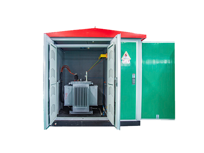
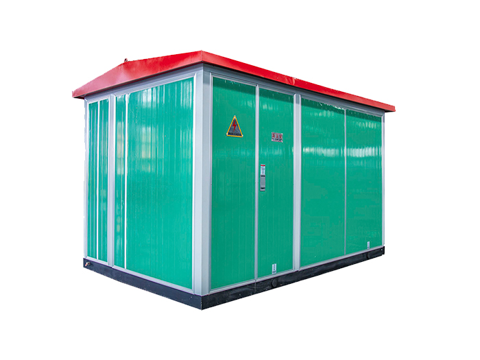
Intelligent integrated transformer substation
Enclosure Structure & Mechanical Design
Framework Construction
The enclosure section is fabricated from channel steel (C-section) and angle steel, providing high mechanical strength (meets IEC 62271-200 seismic class I requirements).
External cladding utilizes anodized aluminum alloy panels (or optional steel/composite alternatives), featuring:Smooth, flat surface finish for aesthetic appeal
Enhanced corrosion resistance (ISO 9227 salt spray tested)
Base & Access Design
Base frame elevated 300–600 mm above foundation level to prevent water ingress.
All doors swing outward with:Opening angle >90° (equipped with positive stop devices)
Integrated handles and concealed, weatherproof latches (IP54-rated, corrosion-resistant)
Fully sealed, tamper-proof enclosure design per IEC 62271-202 security requirements.


Specification Parameter
Technical parameters table
Nominal voltage kV 12 12
Rated currentA630630
Power frequency withstand voltage within 1 minute kV 42 42
Lightning impulse withstand voltage (BIL) kV95 95
Direct current withstand voltage within 15 minuteskV53 53
Power frequency withstand voltage within 1 minute under zero voltage kV 38 38
Power frequency withstand voltage of the second circuit (within 1 minute)V 2000 2000
Power supply voltage for electric operating V DC24 Dc24
Breaking current under rated load A630
Charging breaking current under rated cable A10 25
Breaking current ünder rated short circuit kA20
Making current under rated short circuitkA5050
Withstand current for 3 seconds under rated short circuit kA2020
Withstand current under rated peak kA5050Mechanical life/time 10,000 10,000
SF6 gas rated pressure (20℃) Mpa 0.035 0.035
Annual leakage rate of SF6 gas % <0.1<0.1
Product Advantage
Thermal Management
Natural ventilation system with optimized airflow channels and thermal insulation barriers ensures:All electrical components operate below maximum allowable temperatures (per IEC 60076-2)
Prevention of condensation under ambient temperature variations (−25°C to +40°C)
Dedicated Grounding System
Copper grounding conductor (min. cross-section 30 mm², current density ≤200 A/mm²) installed throughout the enclosure.
Grounding terminals:≥2 fixed connection points for grounding grid (clearly marked with IEC 60417-5019 symbol)
Copper bolts (min. diameter 12 mm, metric thread M12)
Performance requirements:Withstands maximum short-circuit current without thermal damage (per IEC 60909)
Dynamic and thermal withstand capability matched to HV switchgear grounding configuration (tested per IEC 62271-1 Annex BB)
Ensures no hazardous temperature rise on adjacent structures during fault conditions
Outline And Mounting Dimensions