
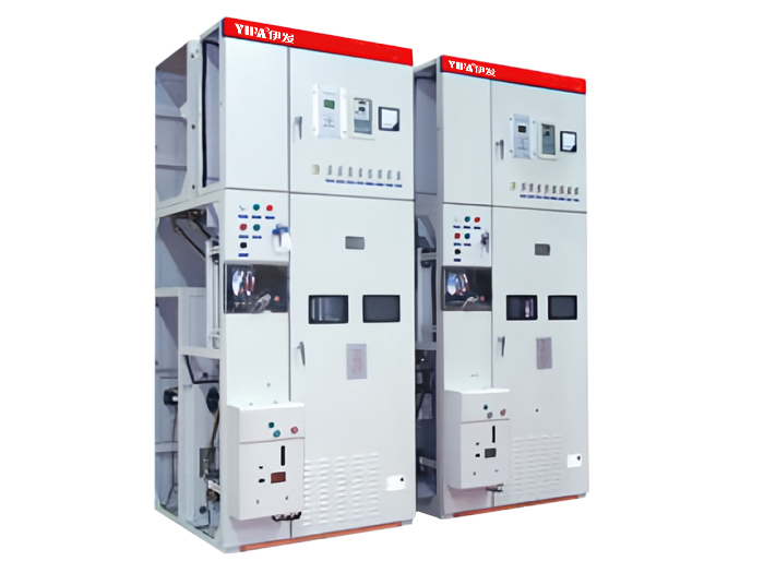
XGN2-12 Box-Type Fixed Metal-Enclosed Switchgear
XGN2-12 Box-Type Fixed Metal-Enclosed Switchgear (hereinafter referred to as “the switchgear”) is designed for 3.6 kV, 7.2 kV and 12 kV three-phase AC 50 Hz networks to receive and distribute electrical energy, especially in installations that demand frequent switching operations. Its busbar system employs a single-busbar arrangement, which can be extended to a single-busbar with transfer bus or a double-busbar configuration.
The switchgear complies fully with the Chinese national standard GB 3906 “3–35 kV AC Metal-Enclosed Switchgear” and the international standard IEC 298, and fulfils the complete “five-prevention” interlocking requirements.
The main switching device is either the ZN28A-12 or ZN22-12 series vacuum circuit-breaker, operated by the CD17A electromagnetic mechanism or the CT19B spring-operated mechanism. The disconnectors employed are the GN30-12 rotary disconnector series and the GN22-10 high-current disconnector series.


Specification Parameter
| Item | Unit | VSI |
| Rated voltage | kV | 3.6,7.2,12 |
| Rated current | A | 630,1250,1600,2000,3150 |
| Rated short circuit opening current | kA | 16,20,31.5,40 |
| Rated short circuit breaking current(peak value) | kA | 40,50,80,100 |
| Rated short circuit stable moving current (peak value) | kA | 40,50,80,100 |
| Rated heat stable heating current | kA | 16,20,31.5,40 |
| Rated heat stable heating time | s | 4 |
| Protection grade | IP2X | |
| Structure type | Single bus bar disjunction and single bus bar with branches | |
| Operation mode | Electromagnetic, spring and energy storage type | |
| The external dimension width*depth*height | mm | 1100X1200X2650(common type) |
| Weight | kg | 1000 |
Product Advantage
The XGN2-12 switchgear is a metal-enclosed cubicle-type structure. The cabinet frame is welded from angle steel, and the interior is divided into several compartments: circuit breaker compartment, busbar compartment, cable compartment, and relay compartment, with steel plates separating each compartment.

The circuit breaker compartment is located in the lower front section of the cabinet. The movement of the circuit breaker is connected to the operating mechanism via a linkage rod. The upper terminal of the circuit breaker connects to the upper disconnector, while the lower terminal connects to the current transformer, which in turn connects to the lower disconnector. A pressure relief channel is also provided in the circuit breaker compartment. In the event of an internal arc, gases can be discharged through this passage to relieve internal pressure.
The busbar compartment is located in the upper rear section of the cabinet. To reduce the overall height of the cabinet, the busbars are arranged in a triangular ("triangular") configuration and supported by porcelain insulators with a bending strength of 7,350 N. The busbars are connected to the terminals of the upper disconnector. Adjacent cabinets' busbar compartments can be isolated from one another.
The cable compartment is located at the lower rear section of the cabinet. Support insulators within the compartment may be equipped with voltage monitoring devices. Cables are secured to brackets. When the main wiring configuration is a tie scheme, this compartment serves as a tie cable compartment. The relay compartment is located in the upper front section of the cabinet. An installation panel inside allows mounting of various relays and other devices. Terminal block supports are provided, and indicating instruments, signal components, and other secondary devices can be installed on the door. Secondary miniature busbars can also be arranged at the top of the compartment.
The circuit breaker operating mechanism is mounted on the lower left front of the cabinet. Above it are the operating and interlocking mechanisms for the disconnectors. The switchgear is designed for bi-directional maintenance: the front is used to service secondary components in the relay compartment, maintain the operating mechanism, mechanical interlocks, transmission parts, and inspect the circuit breaker; the rear is used to service the main busbars and cable terminations. A lighting lamp is installed in the circuit breaker compartment. A grounding copper busbar with a cross-section of 4×40 mm is located below the front door, running parallel to the cabinet width.
Mechanical Interlocking: To prevent:
Operating disconnectors under load;
Incorrect tripping or closing of the circuit breaker;
Unauthorized access to live compartments;
Closing the earthing switch while energized;
Closing the circuit breaker with the earthing switch engaged;
the switchgear incorporates corresponding mechanical interlocks. The principle of mechanical interlocking operation is as follows:
(1) Power-Off Operation (from "Running" to "Maintenance"):
The switchgear is initially in the service position, with both upper and lower disconnectors and the circuit breaker closed. The front and rear doors are locked, and the equipment is energized and in operation. At this time, the selector handle is in the "Service" position. First, open the circuit breaker. Then insert the operating handle into the operating hole of the lower disconnector and pull downward to open the lower disconnector. Remove the handle, insert it into the upper disconnector’s operating hole, and again pull downward to open the upper disconnector. Remove the handle, then insert it into the earthing switch operating hole and push upward to close the earthing switch. Now, turn the selector handle to the "Maintenance" position. The front door can now be opened. Use the key located behind the front door to unlock and open the rear door. The power-down procedure is now complete, and maintenance personnel may service the circuit breaker and cable compartments.
(2) Power-On Operation (from "Maintenance" to "Running"):
After maintenance is completed and power restoration is required, proceed as follows: Close the rear door and retrieve the key, then close the front door. Turn the selector handle from the "Maintenance" position to the "Isolate & Lock" position. At this position, the front door is locked and the circuit breaker cannot be closed. Insert the operating handle into the earthing switch operating hole and pull downward to open the earthing switch. Remove the handle, insert it into the upper disconnector's operating hole, and push upward to close the upper disconnector. Remove the handle, insert it into the lower disconnector's operating hole, and push upward to close the lower disconnector. Remove the handle, then turn the selector handle to the "Service" position. The circuit breaker may now be closed to restore power.
Outline And Mounting Dimensions